Space Shuttle Launch Complex 39-B Construction Photos
Page 55
Kai MacLaren, Earliest RSS Images, James MacLaren (Original Scan)
Top left: My son. The Light and The Rudder of my life.
Top and Bottom Right: What I believe to be the two earliest photographs I took of the RSS. The bottom truss was laid down upon the falsework, and then very large structural pipe weldments were then welded down and added onto, piece by very large piece. Of interest, in the bottom right photo, please notice that the diagonals going down toward the 135 level truss at column line 7 do not actually connect at their lower ends. When the vertical members of line 7 arrived, they would have "stub clusters" that would butt up against the existing pipe framing which would then be full-penetration welded to the existing steel. Those stub clusters were a certified nightmare to cut, fit, and weld. This was pre-computer, and it was all done by hand. It's hard to even imagine the trickiness that's involved where six or eight separate cylindrical structural pipes all come together. And in at least one case, things weren't done quite right on the shop floor, and slipped past the QC inspection, and were only discovered to be bad when they failed to mate with the adjacent pipe framing, up in the air, on the tower. And as a result, we were serenaded by the Infamous Wilhoit Air-arc down in the field trailer, as the ironworkers removed the offending stub, and had to weld on a new one. I'll never forget that sound as long as I live. Lotta time and money down a hole with that kind of thing.
Bottom left: Me under the RSS, with Column Line 7 in the background. The interestingness with this shot revolves around the little yellow drive cab behind me. The RSS is driven around on its track between the mate and demate positions. Somebody sits inside of that cab, and drives the RSS. The truly psychotic thing about it is that the seat they sit on HAS A SEATBELT. What were they thinking when they spec'd out that?!? Here's this gillion-pound steel structure that moves at less than a walking speed, on a rail, and they decided to put a seatbelt on the seat? How, exactly, is that going to make anything in the world safer? Were they expecting the RSS to suddenly lurch forward at sixty miles per hour and wind up in a ditch somewhere? Did they think that if the whole thing fell down that the seatbelt would keep its wearer safe? Personally, I think it's because they wanted the driver to go down with the ship if anything ever happened. "Yeah, we'll tie him in there. He'll never get out in time. That'll serve him right."
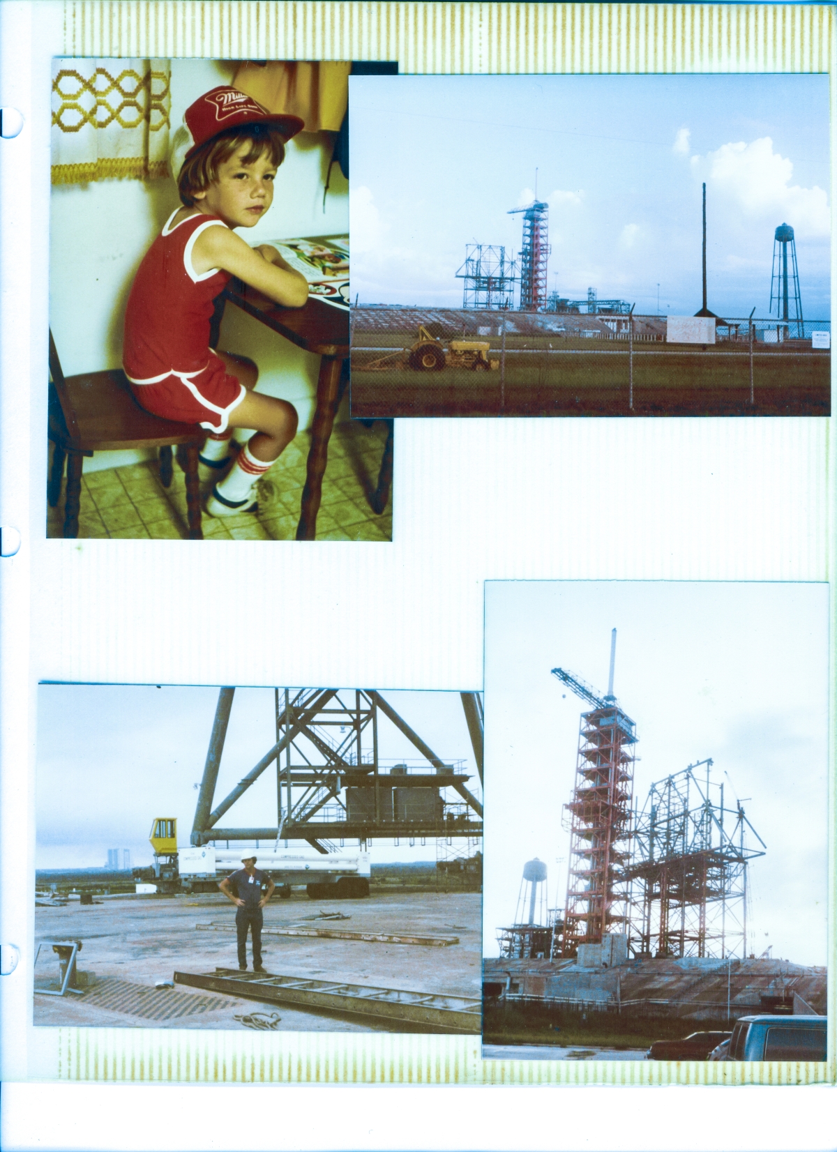
Top Left: (Full-size)

Kai.
This is the guy I came home to after my day at work.
This is the guy who I shared the wonders of the world with, every chance we got.
This is the guy who fills the sails of my life with a fair wind.
This is the guy.
Top Right: (Reduced)
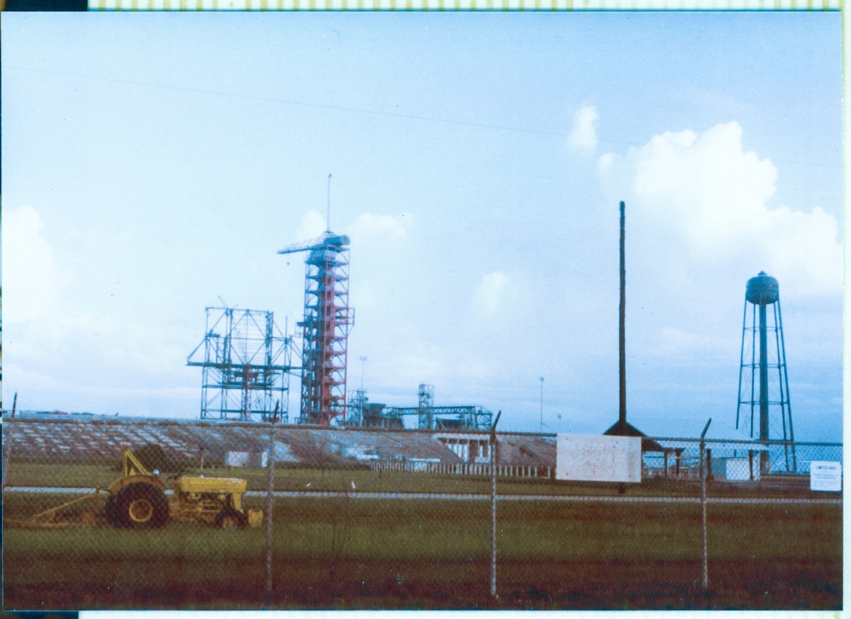
This photograph and the one beneath it are the two earliest images I took of the RSS as it was being built by Wilhoit.
I cannot guarantee it, but I feel comfortable in saying both images were taken the same day, and the time-frame would be somewhere near July, 1980. We have a dated image from June 1980 with which to compare this one and thereby establish a reasonable date, and we will be getting into that when we deal with the next image.
For now it's enough to simply take in the large-scale aspect of things as depicted in this photograph.
It is summer in Florida.
The grass in the foreground is getting deep, and as part of the never-ending battle against the jungle and swamp that never stops encroaching, never stops attempting to retake all that it once owned, a tractor with a bush hog is parked just outside the Perimeter Road, near the Perimeter Fence.
In the distance, you're seeing vegetation working patiently, diligently, endlessly, to cover the concrete of the pad itself, starting from narrow cracks and crevices between individual pieces of poured concrete, and then expanding from there. This pad had lain dormant for a very long time, and now that it was being brought back to active status once again, the battle against Florida's vegetation had been rejoined. Ultimately, in the end, the plants must be the victors, and will once-again hold sway over the landscape. Until the sea retakes it all and puts an end to everything having to do with dry land.
The early-morning heat and humidity of Florida shows clearly in the look of the ground and the sky for those with the eye to see it.
The FSS is still red.
The RSS has yet to properly exist, and at this point consists only in rudimentary stick-drawing form, although the individual "sticks" are serious iron.
This image, despite it's rough appearances, will take a surprising amount of zoom and still yield sensible information, and for the purposes of describing what comes next, I have it open in a separate window at 600 percent(!) enlargement.
The Hinge Column (which is also Column Line 1) has reached its full height, although nothing is tied to it at its top.
The RSS Bottom Truss is complete, of course, since that was the first thing that went up, and it was laid on top of the falsework as a single gigantic weldment.
The great crossed diamond which forms the back wall of the PCR (the PCR has no sensible front wall, since that's where the doors open up to receive, service, and emplace payloads into the Shuttle's Payload Bay) is complete. The portions of Column Lines 3 and 5 between Lines A and B, which form the lateral walls of the PCR are mostly complete.
Lines 2 and 6 are incomplete, and Line 7 does not yet exist at all.
Line A is mostly complete, Line B is getting there, and Line C does not yet exist.
I shall leave it as an exercise for the reader to work out the details of such main structural framing as I have not specifically pointed out with highlighting on the drawings as having been erected, and which is showing in the photograph.
For the purposes of clarity, "main structural framing" consists only in those structural elements making up the lettered and numbered column lines, plus any equally-substantial diagonal pipes or wide-flange beams tying things together at the distinct nodes which can all be located and indicated with a combination of letters, integer numbers, and any of the three main-framing elevation levels at 134'-2", 171'-2", and 208'-2". (Note: "Top of steel" [T.O.S.] for the floor steel which rested upon the main framing at elevation 134'-2" was at elevation 135' and all steel in this area, main framing and floor steel, was invariably referred to as "135" steel, which is how I've been doing it all throughout these stories up to this point, and will continue to do. As an additional note, the elevations for the main framing pipes were given for the centerline [the little ℄ symbol which you may have noticed here and there on the drawings] of those pipes, and the elevations for what was mostly wide-flange beams, which made up the floor steel and other framing steel, was given for the top of the top flange [which you may have noticed here and there on the drawings as "T.O.S."] of those beams. If you weren't careful, that sort of thing could throw you.)
The merest glance at the photograph shows there is a lot of additional steel, above and beyond the main framing, which is showing as erected.
Returning to the drawing which shows main framing lines 2, 3, 5, and 6 with highlights indicating which structural elements are in place, we are looking at a perfect example of one of the very first tasks my boss Dick Walls entrusted me with, as it slowly dawned on us both that I had some sort of gifted eye for this stuff.
Sheffield's contract with Briscoe was written such that incremental payments were made as steel was delivered, and steel was incrementally fabricated and delivered from the shop in Palatka on a schedule that kept ahead of Wilhoit's erection in a way that ensured there would never be any costs incurred from Wilhoit to Sheffield in the form of backcharges if and when Wilhoit became unable to further prosecute the erection process because of steel that had not been delivered in a timely manner. Therefore it was very important to keep close track of both deliveries to the pad (which is another of the very first tasks I was given) and erection of the steel. Deliveries were marked on the detail drawings and on the delivery lists in yellow highlighter, and steel that had been erected was marked in pink highlighter on the erection drawings, and so it fell to James MacLaren to physically go out into the field, visit the shake-out yard on the pad deck, or climb up on the iron, with such delivery and/or erection paper as might be required, and mark things off, first as delivered, and then again, as they were erected, and then return to Sheffield's field trailer and take the information from the oftentimes crumpled and dirty paper which had been worked with up on the tower, and transfer it to the much neater and much more well-organized drawings and paperwork which stayed permanently in the field trailer.
This example of the RSS Main Framing, as shown in this photograph and linked drawings, gives you an idea of what must be done to stay on top of things in a way that allows for prompt payment as well as defense against backcharges, and it seems simple and straightforward enough in this example which involves only the main framing steel.
Things could get a little hairy in other places, with secondary framing steel and miscellaneous metals, though, and occasionally it could be a right bitch for someone who was still in the process of trying to figure out how to do this stuff, to successfully go find and properly identify something that Wilhoit had erected, in order to mark it off on our own set of drawings, and thereby keep abreast of things in a bewilderingly ever-changing environment.
Bottom Right: (Full-size)
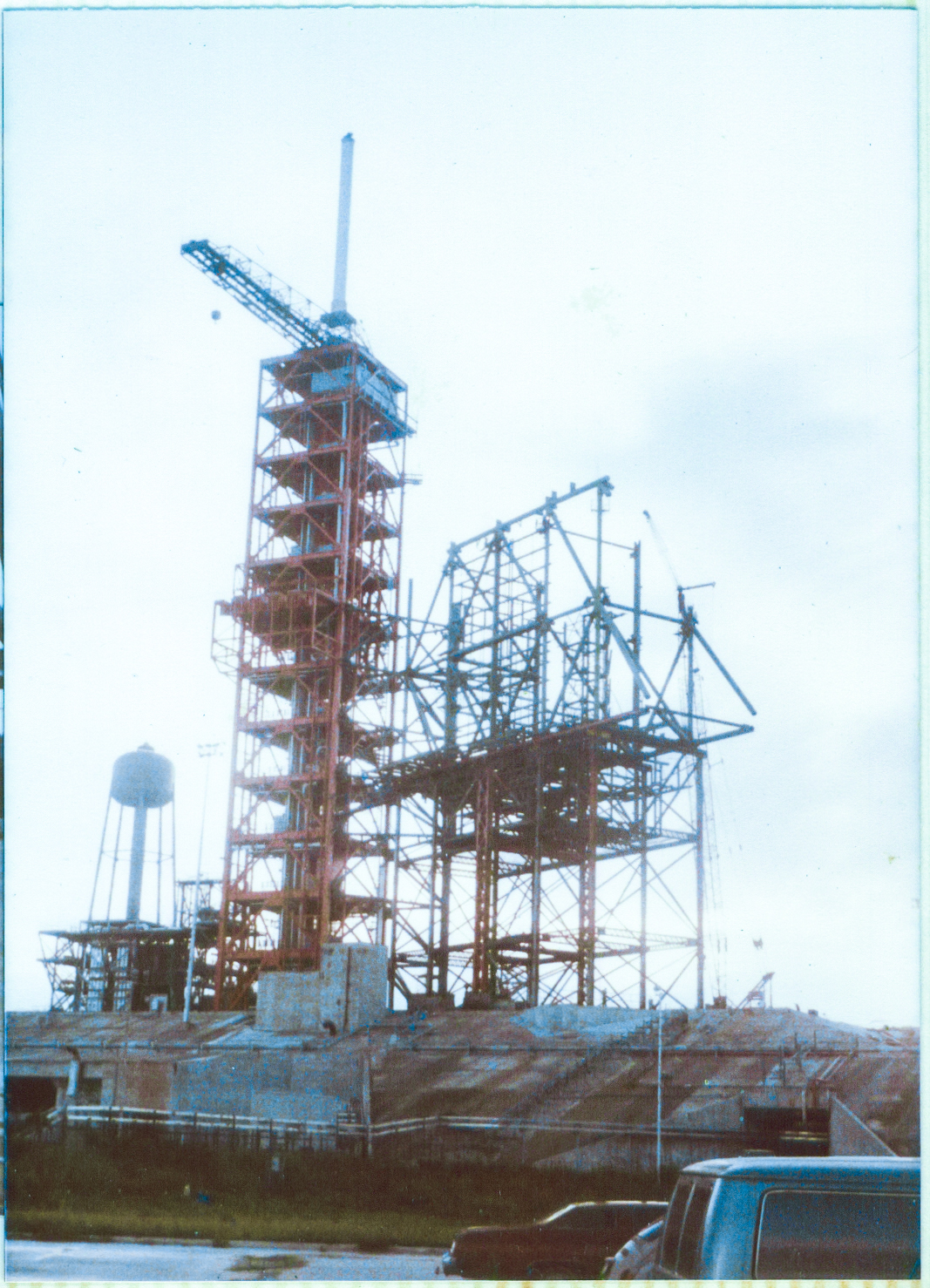
Midsummer, 1980. We can compare this photograph with the dated sketch from "June 1980" by myself that we saw on the previous page, to see the similarities, and the differences, between the two images.
And it's still pretty confusing, so I went ahead and took my best, less than fully-accurate in multiple ways, guess, and faded out all of the RSS structure showing in the photograph, which is not showing in the sketch, and you wind up with something that's much easier to relate to and understand.
Maybe open up the two previously-linked versions of the same drawing, one with RSS framing shaded out, and the other one showing it complete, in two separate browser tabs, and flip back and forth between them to see the differences. Blinking them back and forth provides an interesting look at how things were erected by Wilhoit.
Keep in mind, please, that although the distance between the location where I took the photograph in the parking lot by the cars, is not more than thirty or forty feet away from the location where I was sitting at my desk when I did the sketch, the differences in perspective are significant, and in particular, the location of the Hinge Column as regards its position amongst the welter of other steel framing members, is confusingly different, and in the photograph it lines up near-perfectly with the vertical main framing at Line A-3 (offset the barest bit to the right), whereas in the sketch, it's lined up nearly midway between Lines A-3 and A-4, and in addition to that, in the photograph it is full-height, whereas in the sketch, it appears to be unfinished, and not yet full-height.
Also, in the sketch, Wilhoit was still working with two cranes, and both crane booms appear in the sketch, so that too is a complicating factor in comparing these images with each other. As I mentioned earlier, things can get a little hairy when you're trying to make exact sense of it.
Structural steel can be extraordinarily difficult to understand, even when you're looking directly at it.
And now that I look at things with the RSS faded out, I can see that Wilhoit has hung a very substantial amount of iron between the time the sketch was made and when the photograph was taken, so maybe the photograph was taken in perhaps... July? August? Pretty sure it wouldn't be September, 'cause primary, and heavy-secondary iron goes up extraordinarily fast. Way faster than people think it should. There's really not much difference (large full-penetration welds excepted) between hanging heavy iron and light iron except for the fact that each piece of heavy iron is much larger, and therefore fills things in much quicker, and there's a lot less of it, so there's lots less connecting that needs to be done. So yeah, heavy iron goes up in a hurry, and as an example of that, remember that when I first arrived at the pad, the falsework had only just been started, and was nowhere near complete, and that was March 17, 1980. Presume the sketch was made in mid-June, and that means all of the RSS and falsework steel in the sketch had been done 90 days, or less, most likely significantly less. So again, heavy iron goes up in a hurry, ok?
Of note in this image, there appear numerous dark "clumps" that can be seen at and near places where main framing steel comes together at connection points. Some of these "clumps" (and in particular the lighter-shaded ones) are structural pipe stub-clusters, but other "clumps" are ironworkers, working the connections, be it welding, grinding, torching, or whatever else might be required to bring any given connection to a finished state, ready to bear the full set of forces generated by whatever loads it was designed to take.
Bottom Left: (Reduced)
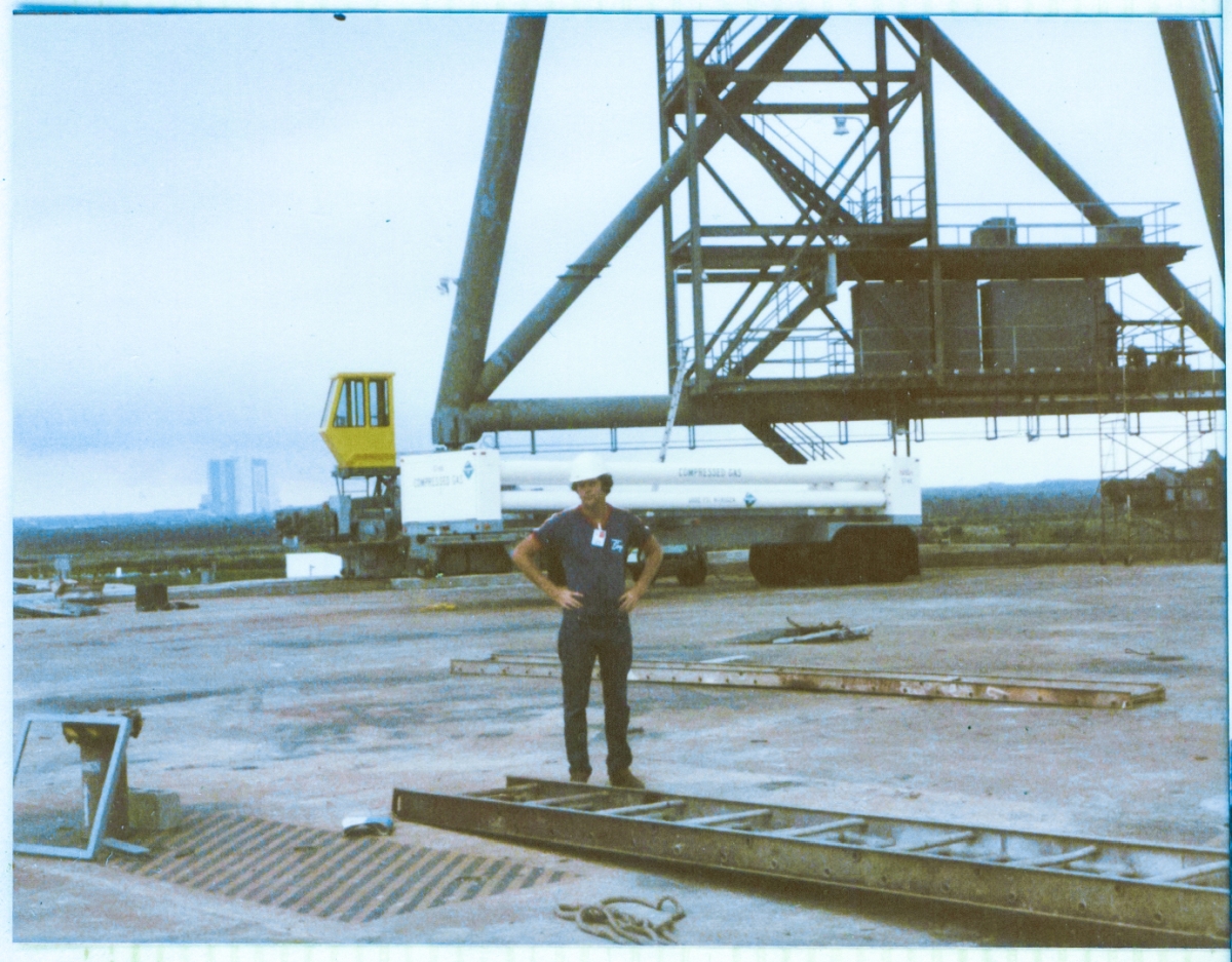
James MacLaren stands beneath the RSS following the removal of the falsework that held it up during its erection by Union Ironworkers working for Wilhoit Steel Erectors. A high-pressure gas trailer sits in front of the Column Line 7 steel, and the yellow Drive Cab sits on top of the Forward Drive Truck for the RSS, most of which is hidden behind the gas trailer. On the pad deck, the detritus of an active construction site completes the scene.
Return to 16streets.comACRONYMS LOOK-UP PAGEMaybe try to email me? |